Computer Assembly - How To Assemble A PC
Install The Motherboard Into The Computer Case
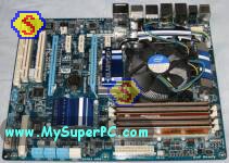
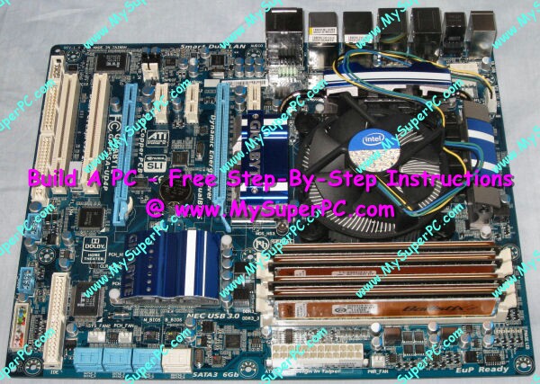
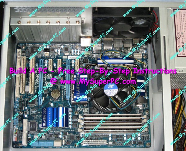
The motherboard is ready to be installed in the computer case. At this point, the processor, CPU cooler and memory modules have been installed onto the motherboard so it looks like this.
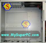
Remove the right-hand panel from the computer case and lay the computer case on its side. The motherboard will lay flat inside the case, resting on brass-colored mounting posts.
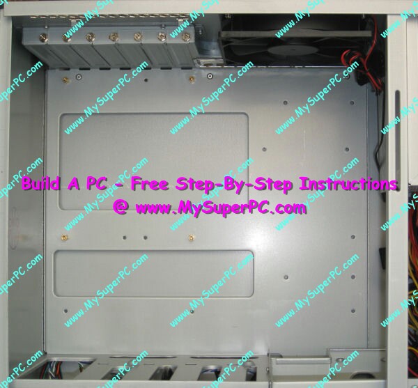
This shot is taken looking straight down into the case at the position in which the motherboard is to be installed. The orientation of the motherboard when it is inside the case is the same as the picture of the motherboard above. It's easy to see in the enlargement of the picture below that the case comes with four brass-colored mountings posts already installed. There are holes in the case for additional mounting posts, but not all of them are appropriate for all motherboards.
The motherboard is ready to be affixed to the case. This is done using fasteners that came with the computer case, shown in the picture below. What's needed are some, but not all, of the brass-colored mounting posts shown in the center of this picture, as well as some, but not all, of the mounting post screws shown in the lower-left of this picture. At this point, pair up screws that fit easily into a corresponding mounting post, including the four mounting posts pre-installed inside the case.
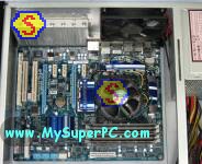
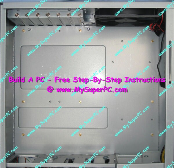
The motherboard is affixed to the case by inserting mounting post screws through holes in the motherboard and into the mounting posts. The first step is to determine in which case holes the mounting posts should be installed. The Gigabyte P55A-UD4P motherboard has nine holes for using with mounting posts. Place the motherboard down into the case, aligning four of the holes in the motherboard with the four pre-installed mounting posts. All four pre-installed mounting posts align with motherboard holes in the Gigabyte P55A-UD4P. In addition, all five of the remaining holes in the motherboard have a corresponding case hole for a mounting post, so five additional mountings posts can be installed. The five additional mountings posts should be carefully tightened (not overly tightened) into place using a 5mm socket wrench. After installing the additional mounting posts, the interior looks like this.
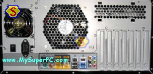
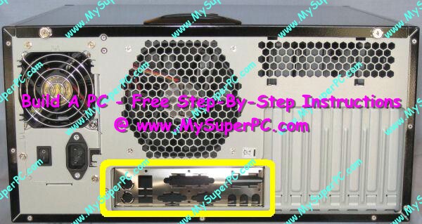
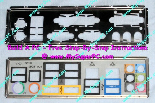
Before lowering the motherboard down in the case, the I/O shield that came installed with the computer case should be replaced with the one that came with the Gigabyte P55A-UD4P motherboard. Some motherboards don't need this step, but many do. You can just look at the I/O shield and see if it looks correct for the motherboard. Here, circled in yellow, is how the I/O shield looks as it comes installed with the Antec Sonata 3 computer case. And comparing the shape, size and holes with those of the connectors on the Gigabyte P55A-UD4P motherboard - it just won't do.
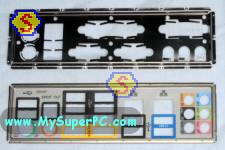
The I/O shield that comes in the retail box of the Gigabyte P55A-UD4P motherboard is shown below in the picture on the bottom. The I/O shield on top is the one removed from the Antec Sonata 3 computer case. Its easy to see that the two are not really very similar.
The I/O shield is uninstalled from the computer case by pushing on the I/O shield to push it into the computer case. It is not held in place by screws. It is simply snapped into place. While pushing on the outside of the I/O shield to push it into the computer case, you'll simultaneously need to loosen the I/O shield from the inside of the case with a flathead screwdriver by gently prying up on the thin metal tabs around the edge of the I/O shield that help keep it snapped into place. Start with a corner and keeping pushing and prying along the edge of the I/O shield as it comes free. Once a long edge is free it will just about fall out. The new I/O shield snaps easily into its place and looks like this.
Now rest the motherboard down inside the case on the mounting posts. Insert the screws through the holes in the motherboard and into the mounting post, getting each screw started but not at all tight - just far enough in the mounting post so the screw does not fall out. I found the screws were easy to place into their holes with just my fingers. In other builds, I have sometimes had to lower them into place with needle-nose pliers. Once all nine have been started, all nine can be tightened into place one at a time.
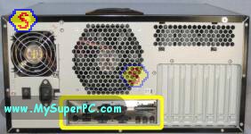
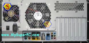
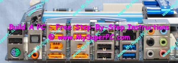
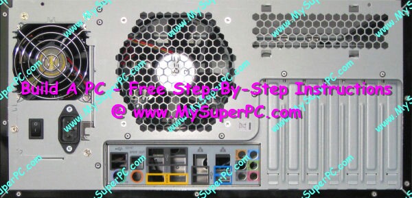
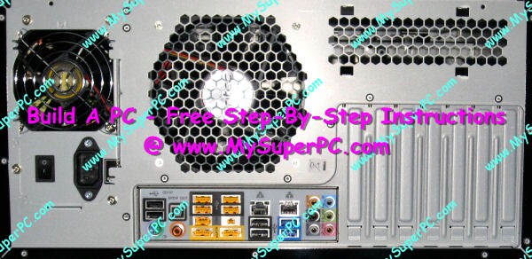
And now with the motherboard installed, this picture of the back of the computer case shows how the input-output ports of the Gigabyte P55A-UD4P motherboard look now that they are accessible through the I/O shield.
Back to My Super PC - Home Page
How To Build A Computer. Step By Step Instructions To Assemble. Skip To Any Assembly Step.
Back to My Super PC - Home Page
© 2001-2015, Rob Williams, all rights reserved.
|

|